
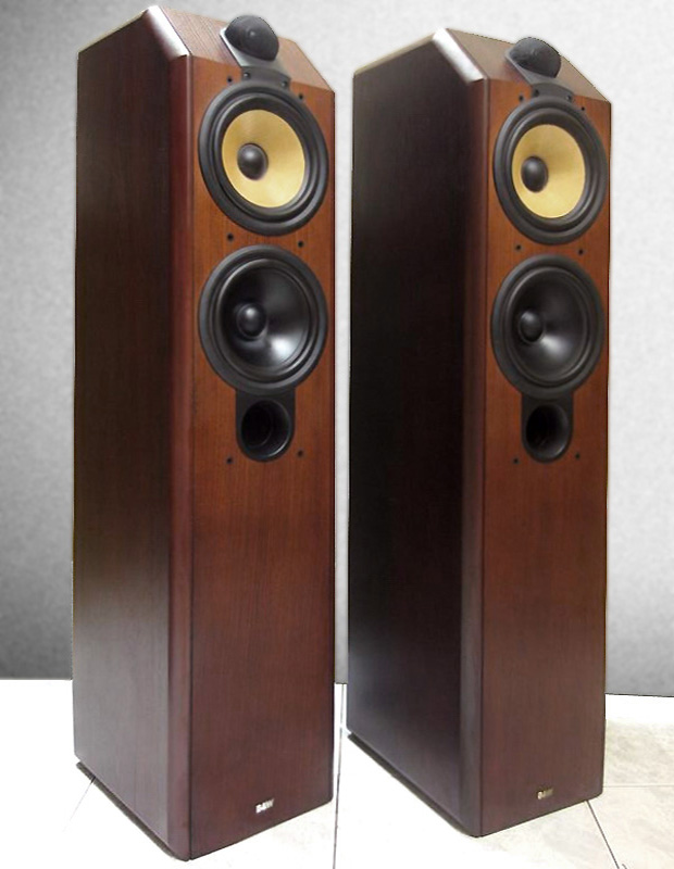
B&W BVR Two-Way
A friend brought me a pair of B&W CDM7 loudspeakers for an advice
how to improve the sound performance. He complained of boomy bass
out of control and lack of balance in the entire sonic spectrum.
To find out the reason for the slack bass, I started with
the measurements of the low frequency drivers. The detailed
measurements can be found here:
Woofer -
B&W ZZ08613
Midwoofer -
B&W ZZ10075
I was surprised, that the frequency response of the woofer
is extended up to 7kHz and its linearity is not bad at all.
The Thiele/Small parameters of both drivers are almost
identical. They share a common volume with one front loaded
basreflex port. With the Qts of 0.32 we could not expect
remarkable performance in lows in a classic bassreflex
construction. That's why designers of the CDM7 decided to
use the lower driver for lowest frequency only.
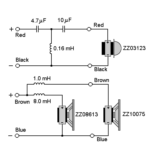
The crossover schematics of B&W CDM7 is simple. The cutoff frequency for the woofer is 160Hz and for the midbass - 1250Hz.
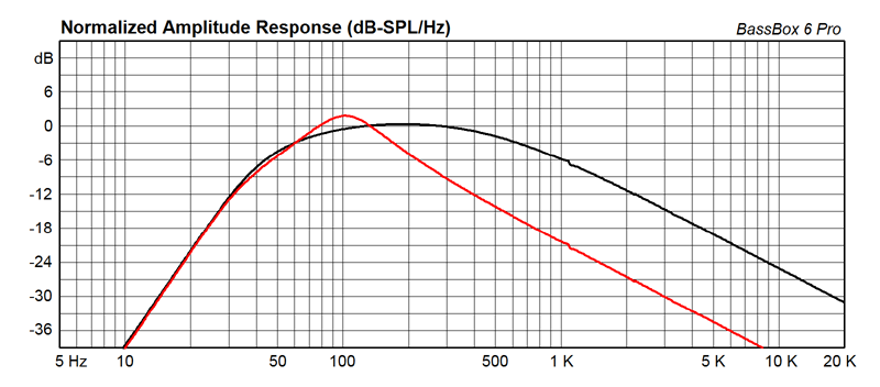
The BassBox simulation of the B&W CDM7 enclosure shows clearly the reason for "bummy" and monotonous bass. The woofer's range (in red) is narrow with a peak at 100Hz. The black curve is for the midbass unit.
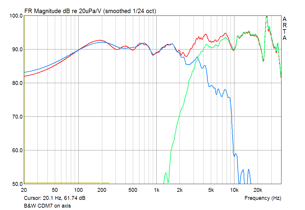
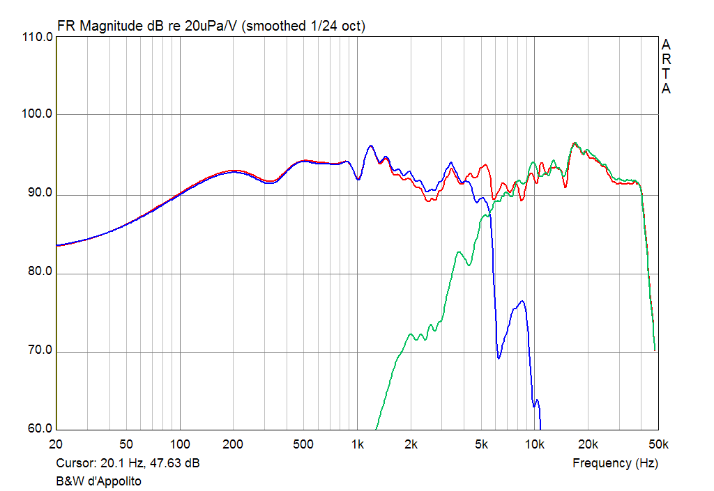
The left graphics show the measurements of the upper(tweeter) and
lower (woofer and midwoofer) section of the system, where the test
signal is applied to the input terminals with enabled bi-wiring
(external junctions were removed). The acoustical crossover
frequency is about 2.3 kHz.
The tweeter in the original crossover has no attenuation. As we see its level is
about 2-3dB higher than the average level in the midrange. Maybe the
reason design engineers did it this way, is to compensate the
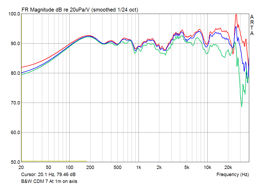
roll-off in the off-axis response, given in the right graphics. Or
maybe with making highs brighter, they tried to mask somehow the
imperfection of the bass fundament ... who knows.
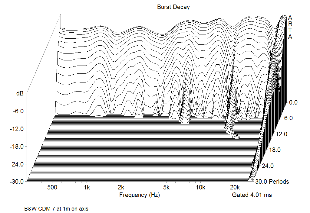
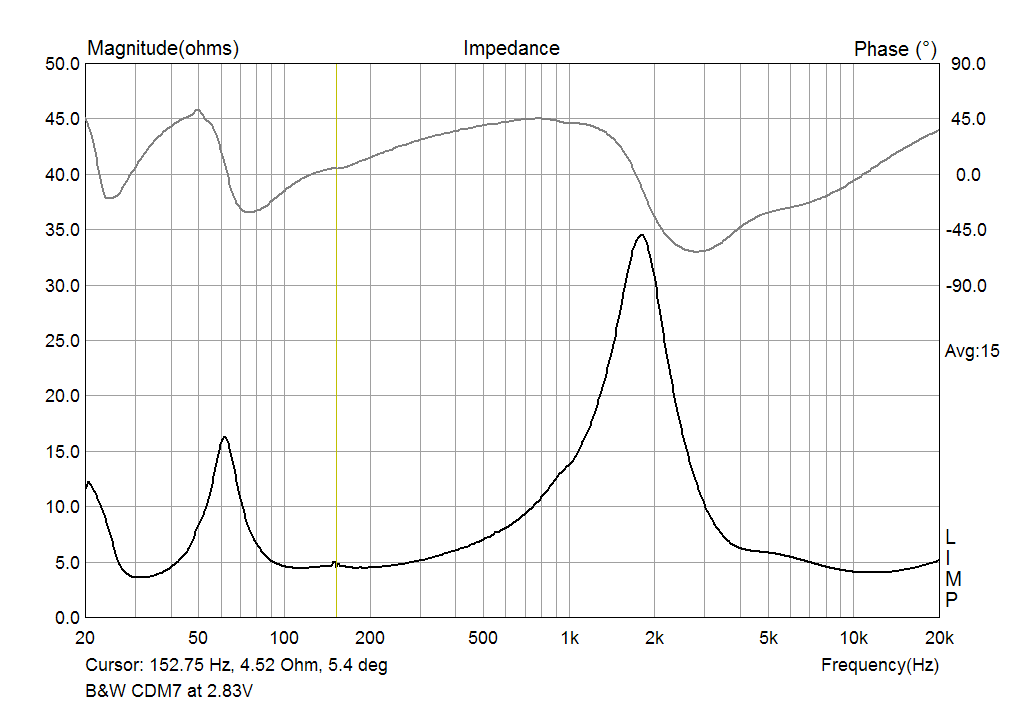
The burst decay looks good, and the impedance curve is normal, with an exception, that the impedance does not match the manufacturer's specification, which is 8 Ω. Since the impedance is going under 4 Ω in ranges around 30Hz and 12KHz, the impedance should be rated strictly 4Ω to avoid a damage of certain amplifiers.
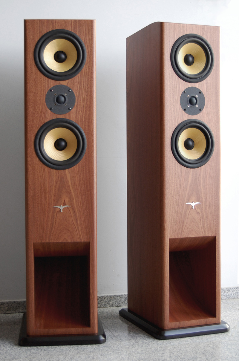
My New Construction
The initial idea was to keep all the original B&W drivers
constructing an enclosure with better bass performance
and improved crossover. After a careful observation of
all the drivers, I found, that one of the tweeters was
damaged. Instead of searching the original tweeter
ZZ03123, which is hard to find now, I decided to use one of
my favorite high-efficiency drivers:
AUDAX TW025A26
This driver has very good off-axis response at a glance and
matches very well with Kevlar drivers I tried it with.
In the new construction the so called 2 1/2 design of CDM 7
was explicitly unwanted and while I tried to avoid this
configuration, my friend solved the problem, finding another
pair of ZZ10075.
This drive can still be found in the
Online Parts Store of the B&W Group website.
Thus we had a matched quad for a two-way d'Appolito
configuration.
After all only a pair of midbasses and the input terminals
left from the original system.
The Thiele-Small parameters of the midwoofers guided me to
apply my beloved Big Vent Reflex (BVR) construction.
For drivers with moderate values of Qts (0.25-0.35) this
design delivers much more efficiency in the low-frequency
reproduction than the ordinary bassreflex. The performance
is faster and does not suffer of humdrum.
The Simulations
| Driver Parameters | Horn Parameters | |||
| Rdc | 5 Ω | Type | Rearloaded | |
| Fs | 34 Hz | Contour | Exponential | |
| Qes | 0.34 | Position | Floor | |
| Qms | 4.7 | Leight Difference dl | 0 m | |
| Vas | 32 ltr | Mouth Height h | 32 cm | |
| Pmax | 50W | Horn Width b | 18 cm | |
| Sd | 160 cm2 | Contour Leifgt l | 0.5 m | |
| Z1K | 10 Ω | Driver Position | 0 m | |
| Z10K | 28 Ω | Mouth Area At | 40 cm2 | |
| Xmax | +/-4 mm | Chamber Volume Vfc | 33 ltr | |
| Number of Chassis | 2 | Coefficient β1 | 40 | |
| Uin | 2.0 V | Coefficient β2 | 0 | |
The table above shows the input parameters for the AJ Horn simulation program.
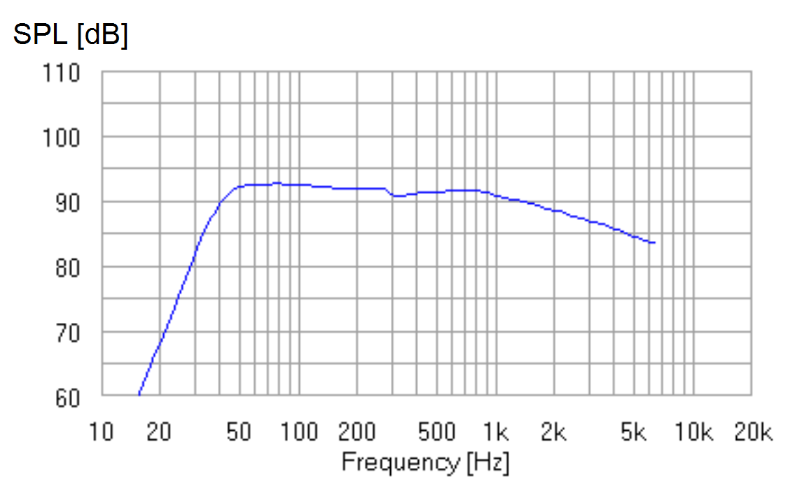
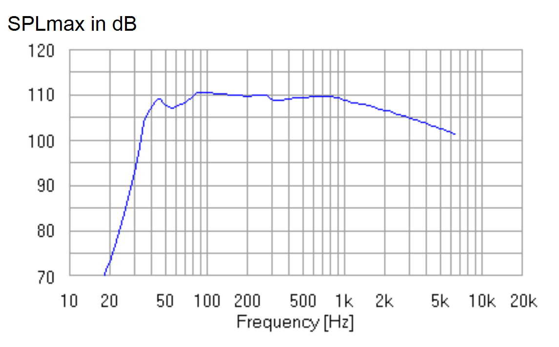
The BVR improves the whole efficiency in the range up to 300Hz. The performance graph shows 40Hz at -3dB and 36Hz at -6dB
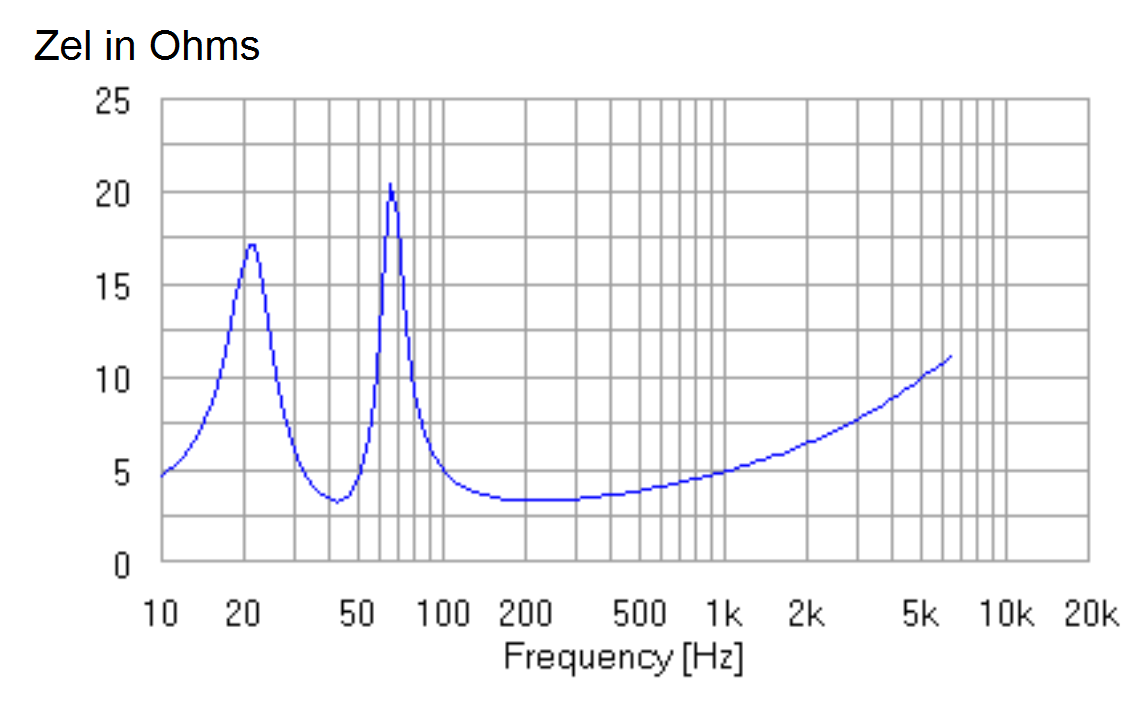
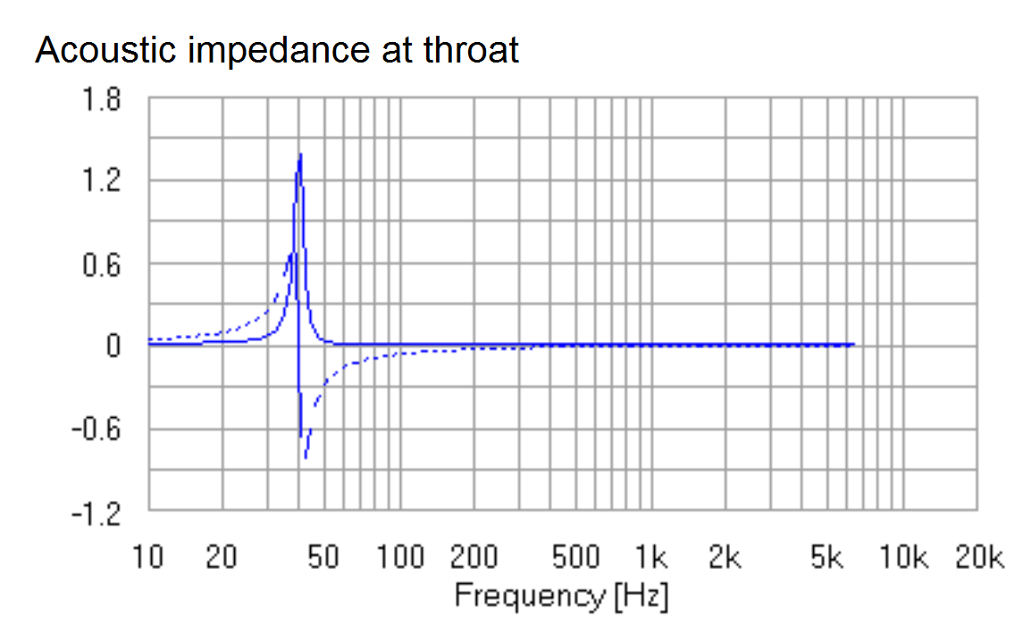
This Electrical and Acoustic impedance without the passive crossover.
The Enclosure
Most parts of this enclosure were made of mid-density
practical board. I do prefer this material to MDF for its
better sonic performance and ability for homogenous
assemblies using glues for wood.
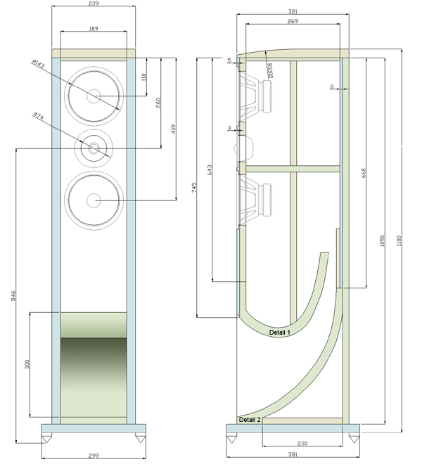
The detailed plans and the part list of the construction can
be found here:
BW BVR Enclosure Plans and Part List ![]()
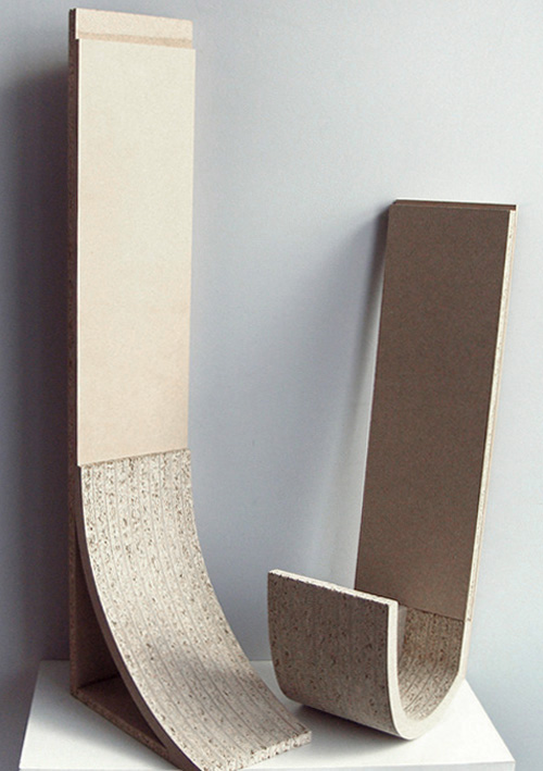
The essential of this construction are Detail1 and Detail2. They are precisely cut of practical board using CNC
router or water jet cutter.
Here is the AutoCad drawing file for both details:
![]()
They are 10 details of each kind for one enclosure with a
thickness of about 18mm. It is important to mention, that
this value varies for each sheet of material, even from the
same manufacturer. To avoid misalignment, they have to be
cut and assembled prior to cut out the other parts. After
the assembly the thickness of the pack should be measured.
This will be the value, market with * in
the part list.
The base and the top were made of 25mm MDF. The top is
formed with radius for aesthetical appearance and it is glued
to the common construction. The bottom is a different part
and it is attached to the bottom using a Confirmat screws.
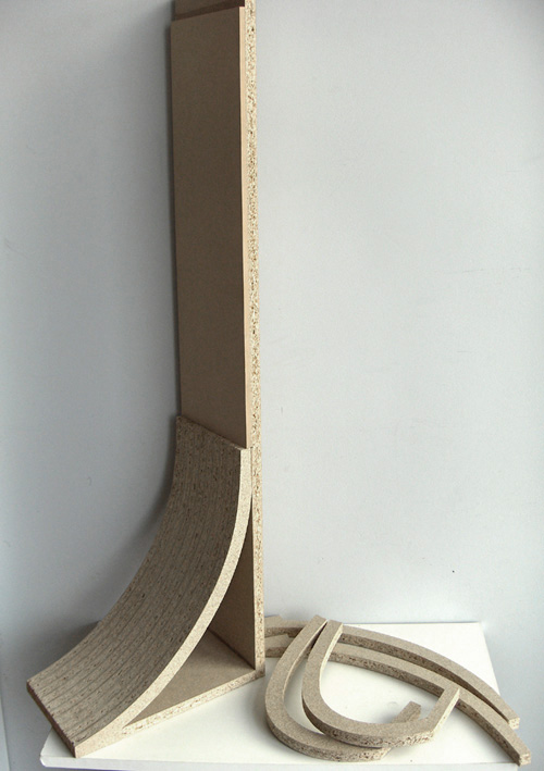
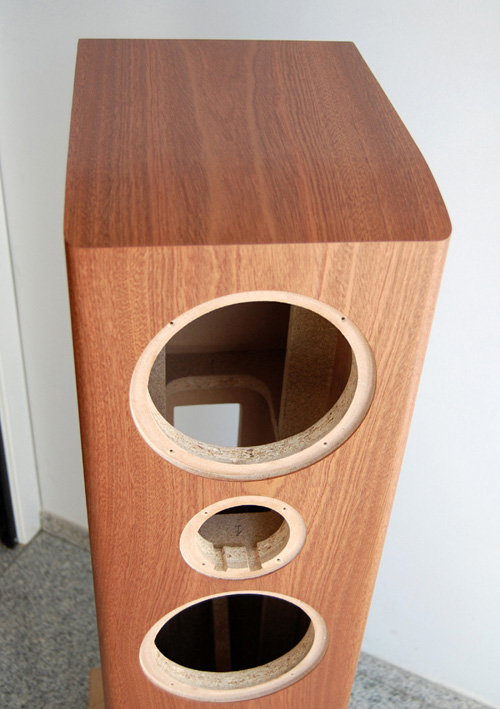
Some photos of the process of assembly. All the drivers were dug into the front panel. For sharper cut it consists of two layers - practical board and HDF, that can be seen in the picture and plans.
The Crossover
They are two approaches in the crossover design. They will be presented in parallel. The Version 1 on the left is a result of my attempts to give the midbass driver more air and to add some tube friendliness using small values for all coils and capacitors. The Version2 on the right is a classical design for best linearity and off-axis performance.
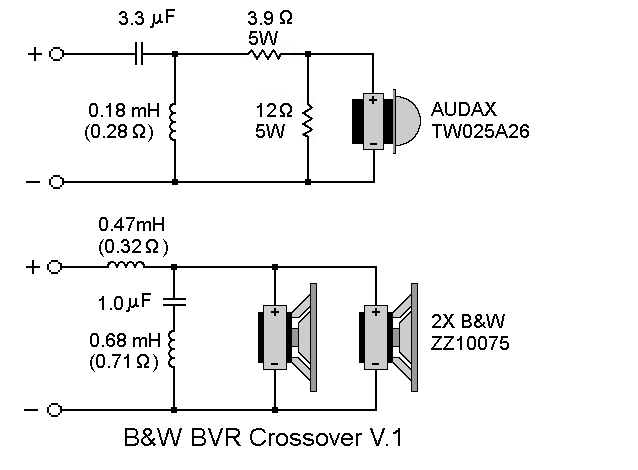
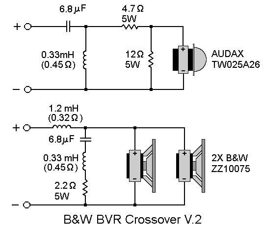
The crossover schematics of both versions.
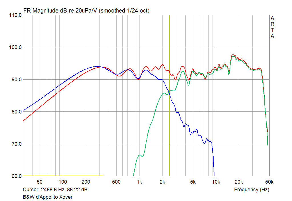
The acoustical crossover frequency is about 5.5 KHz for V.1 and 2.5 KHz for V.2
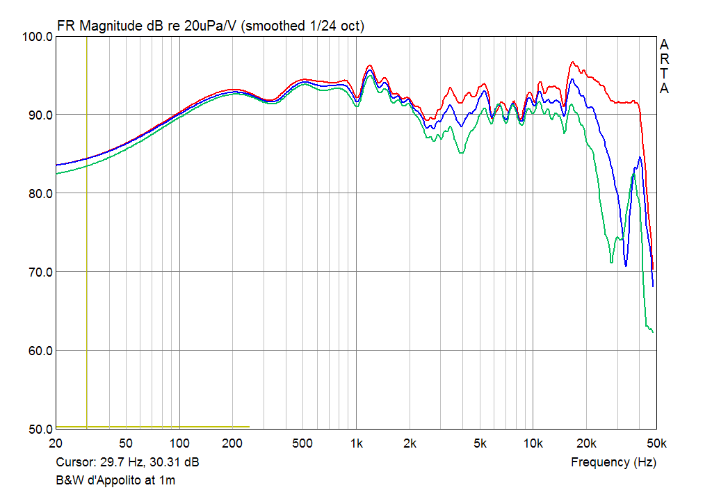
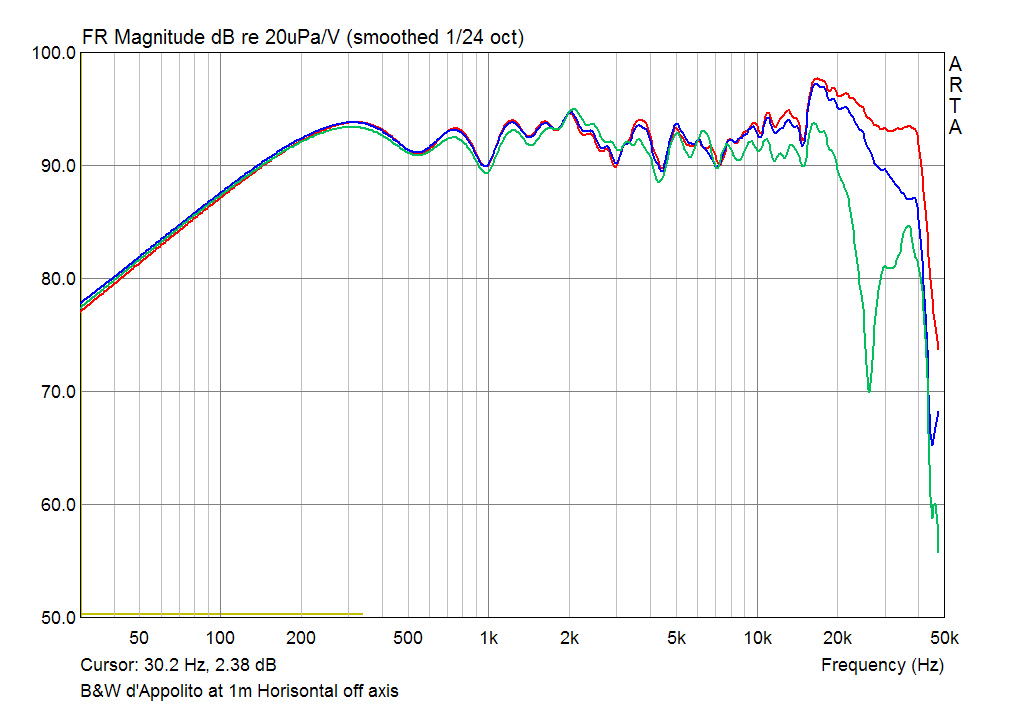
Frequency response at 1m with 2.0 V input RED - on axis, BLUE - 15 º off axis, GREEN - 30 º off axis.
Here it the main difference between two version. The roll-off in the
range of 2-5 KHz of V.1 is easy to observe. The SPL graph of V.2 is
excellent even at 30 º off axis. In fact it is most linear at this
angle.
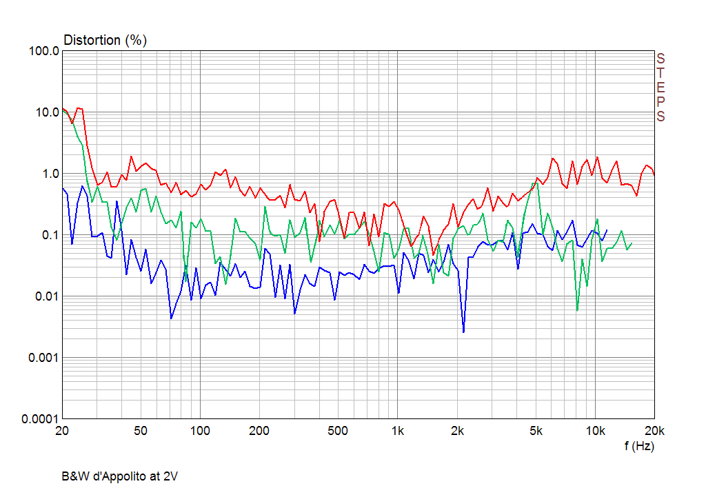
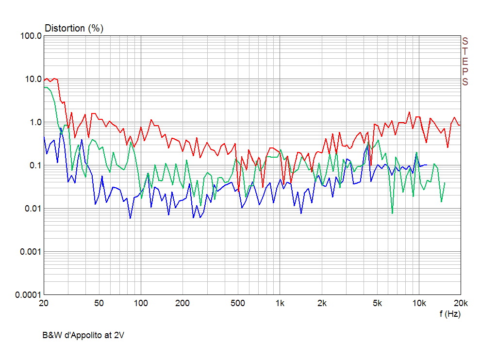
The second, third and fourth harmonic curves measured at 2.0V input RMS. Version 2 has a bit better result.
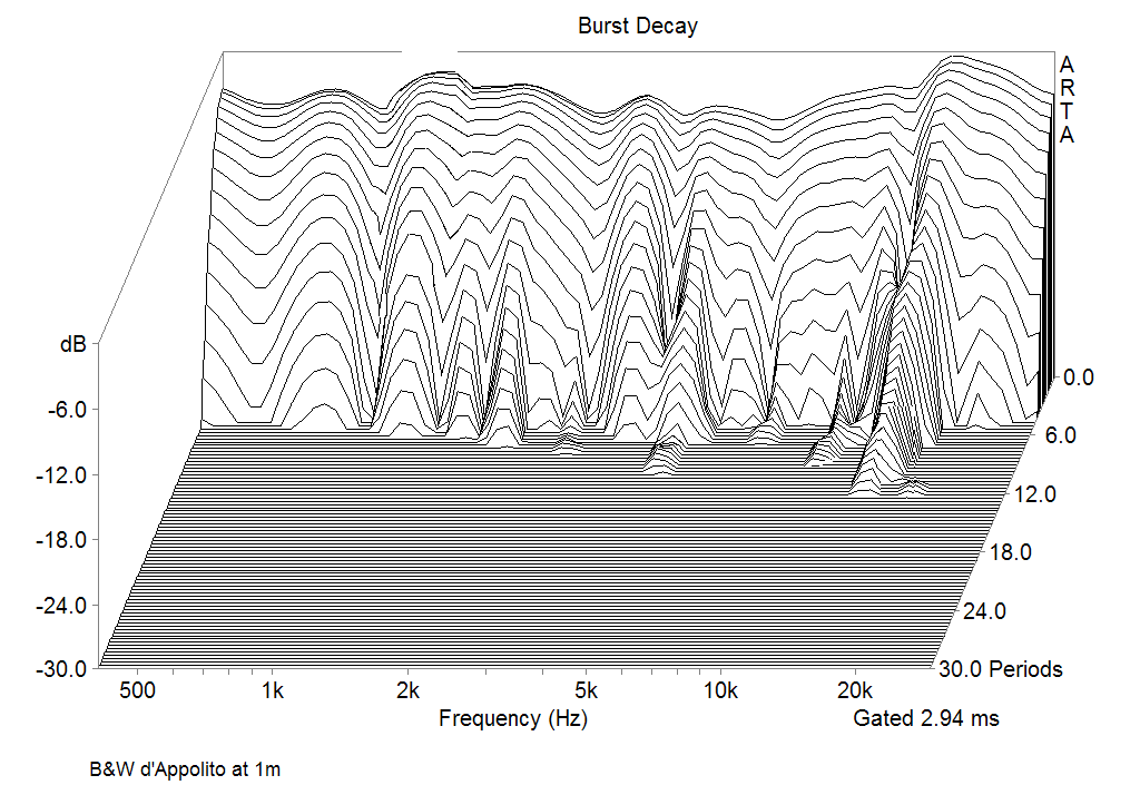
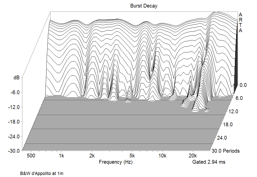
Burst decay response, measured at 1m on axis. Almost the same.
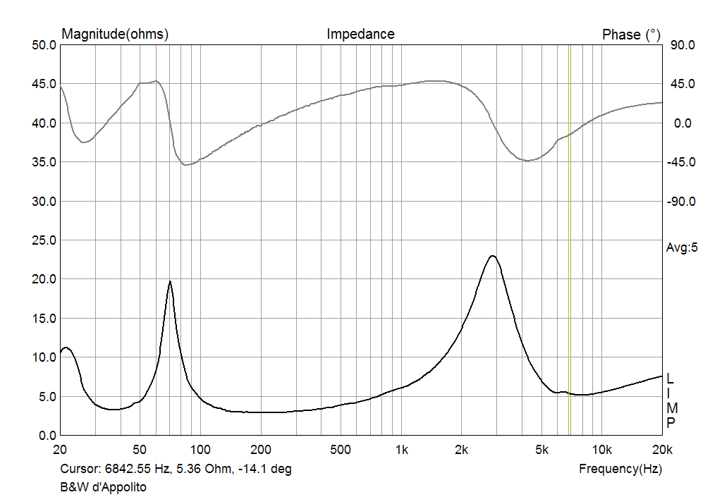
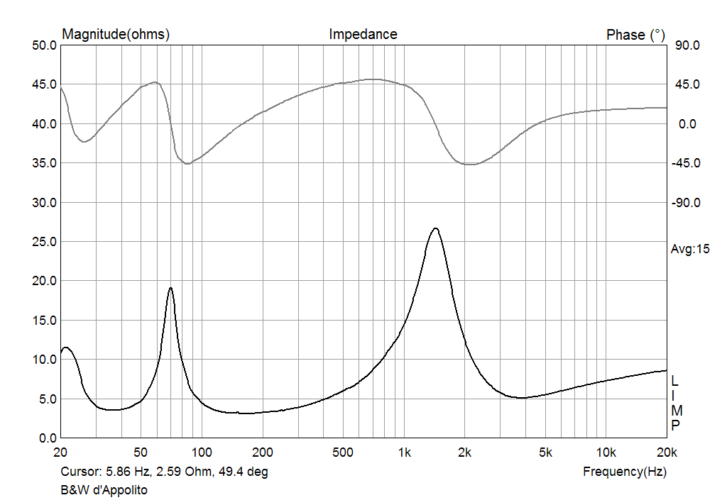
The impedance curves
Conclusion
Some words about the sound. I liked the performance of both two versions and that's why I decided to give them as two options. The V.1 is vivid and bright, with an excellent body and scale of vocals and pianos. The V.2 is linear and tolerant to the placement and position angle with very clear and articular reproduction in the whole range. The bass fundament of whole systems is tight and strong. The midbass drivers are a bit gentle and this is not recommended for this system to be pressed hard by power.